PRIZM Core Neo
1. Introduction
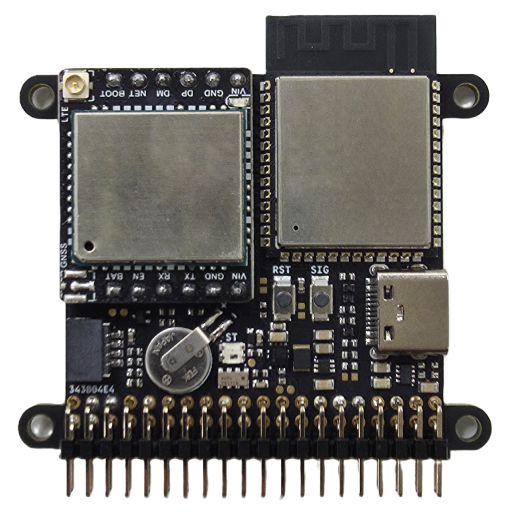
PRIZM Core Neo is a compact IoT controller board designed for fast development and deployment of connected devices. It integrates an ESP32-S3 main processor, Wi-Fi and cellular connectivity, flexible GPIO expansion, USB-C power input, onboard sensors, and time keeping using RTC with backup battery.
PRIZM Core Neo is designed for IoT products that require reliable cloud connectivity, compact mechanical integration, and a simple expansion interface.
2. Product Variants
The standard PRIZM Core Neo model includes LTE cellular connectivity and PCB antenna Wi-Fi.
| SKU | Variant | Cellular | Wi-Fi Antenna | Availability |
|---|---|---|---|---|
| PCN11YP | PRIZM Core Neo Cellular, PCB Wi-Fi | Included | PCB antenna | Standard model |
| PCN11YU | PRIZM Core Neo Cellular, U.FL Wi-Fi | Included | IPEX 1 / U.FL connector | Available upon request |
| PCN11NP | PRIZM Core Neo Wi-Fi Only, PCB Wi-Fi | Not included | PCB antenna | Available upon request |
| PCN11NU | PRIZM Core Neo Wi-Fi Only, U.FL Wi-Fi | Not included | IPEX 1 / U.FL connector | Available upon request |
3. Key Features
- ESP32-S3 main processor
- 2.4GHz Wi-Fi and LTE Cat. 1 bis cellular connectivity
- Built-in LIS2DH12TR accelerometer and RV-3028-C7 real-time clock with backup battery
- Qwiic-compatible I2C connector
- USB-C power input
- Cloud-based OTA application deployment
- 2 x 20 pin expansion header
- Compact 40mm x 40mm board body
4. Cellular Connectivity
| Item | Specification |
|---|---|
| Cellular Technology | LTE Cat. 1 bis |
| Region | Global |
| LTE-FDD Bands | B1 / B2 / B3 / B4 / B5 / B7 / B8 / B12 / B13 / B14 / B17 / B18 / B19 / B20 / B25 / B26 / B28 / B66 / B71 |
| LTE-TDD Bands | B34 / B38 / B39 / B40 / B41 |
| Regulatory / Conformance | GCF, CE, PTCRB, FCC, IC, Anatel, NAL, CCC, SRRC, JATE, TELEC, KC, RCM, NCC |
| Other | WHQL / RoHS |
The cellular model includes a SIM and a data plan with 500 MB of data valid for 10 years.
The cellular antenna is connected through an IPEX 1 / U.FL connector.
5. Wi-Fi Antenna Options
By default, PRIZM Core Neo uses a built-in PCB antenna for Wi-Fi and does not require an external Wi-Fi antenna.
A Wi-Fi model with an IPEX 1 / U.FL connector can be supplied upon request for applications that require an external Wi-Fi antenna.
| Wi-Fi Antenna Type | Description |
|---|---|
| PCB Antenna | Standard configuration |
| IPEX 1 / U.FL | Available upon request |
6. Power Supply
PRIZM Core Neo can be powered through either the USB-C connector or the VIN pins on the 2 × 20 pin header.
| Power Input | Voltage | Description |
|---|---|---|
| USB-C | 5 V | Main power input, primarily used for power supply |
| VIN Header Pin | 5 V | External 5 V power input through the expansion header |
PRIZM Core Neo includes a priority power multiplexer for input power selection. When power is supplied through both the USB-C connector and the VIN header pin at the same time, the board automatically selects the VIN header pin as the active input power source.
6.1 Required Input Current
| Board Version | Minimum Recommended Power Supply |
|---|---|
| Cellular version | 5V, 2A or higher |
| Wi-Fi only version | 5V, 1A or higher |
For cellular models, a power supply capable of at least 2A is recommended to ensure stable operation during LTE network registration, data transmission, and peak current events.
6.2 3.3V Output
The 3V3 pin provides regulated 3.3 V output for external peripherals.
| Pin | Voltage | Maximum Recommended Load |
|---|---|---|
| 3V3 | 3.3 V | 150mA |
Do not exceed 150 mA from the 3V3 output pin.
6.3 VBS Pin
The VBS pin exposes the USB-C VBUS rail directly to the pin header.
This pin can be used as a USB-derived output power rail for a user-designed carrier board or expansion board connected to PRIZM Core Neo.
| Pin | Description |
|---|---|
| VBS | USB-C VBUS output exposed to the pin header |
7. USB-C Interface
The USB-C connector is primarily used for supplying 5 V power to the board.
USB can also be used for firmware download, recovery, development, debugging, or serial console access when required. In normal product operation, applications are typically deployed through the PRIZM cloud system, so USB is mainly used as a power input.
| USB Function | Description |
|---|---|
| Power Input | Primary use of USB-C |
| Firmware Download | Available when required for firmware recovery |
| USB Serial / Console | Can be used for serial console or debugging workflows |
The USB data signals are also exposed on the pin header.
| Signal | Header Pin |
|---|---|
| USB_DN | 4 |
| USB_DP | 6 |
8. Buttons and LEDs
8.1 RST Button
The RST button resets the board.
8.2 SIG Button
The SIG button is connected to the SOFT_SDN signal.
| Press Duration | Function |
|---|---|
| Less than 3 seconds | Can be used for user-defined action |
| 3 seconds or longer | Soft shutdown request |
When the SIG button is held for 3 seconds or longer, PRIZM Core Neo starts a normal shutdown sequence. During this sequence, the board performs tasks such as cloud disconnection and cellular network detach.
During shutdown, the STAT LED rapidly blinks white. When shutdown is complete, the STAT LED turns off.
8.3 STAT LED
The STAT LED indicates the board status.
| LED | Description |
|---|---|
| STAT LED | System status indicator |
Refer documentation page for STAT LED behavior depending on the system status.
8.4 Cellular Status LED
Cellular models include a green LED on the cellular module. This LED indicates cellular communication status.
| LED | Description |
|---|---|
| Cellular green LED | Cellular communication status indicator |
9. Expansion Header
PRIZM Core Neo provides a 2 x 20 pin header with a 2mm pitch.
| Item | Specification |
|---|---|
| Header Type | 2 x 20 pin header |
| Pin Pitch | 2mm |
| IO Logic Level | 3.3 V |
Most GPIO pins can be configured for multiple ESP32-S3 peripheral functions, including SPI, I2C, UART, PWM, ADC, and other alternate functions depending on pin configuration.
For detailed ESP32-S3 pin functions, electrical limits, peripheral multiplexing, and ADC availability, refer to the official ESP32-S3 datasheet.
9.1 Pinout (Front View)

9.1 Pinout (Back View)

10. System Pins
10.1 I2C Bus
PRIZM Core Neo includes an onboard I2C bus connected to the following devices and expansion interface:
- LIS2DH12TR accelerometer
- RV-3028-C7 real-time clock
- Qwiic-compatible connector
- Expansion header pins
| Signal | Header Pin | ESP32-S3 GPIO |
|---|---|---|
| I2C1_SDA | 31 | GPIO39 |
| I2C1_SCL | 32 | GPIO40 |
The onboard I2C devices use the following addresses:
| Device | Function | I2C Address |
|---|---|---|
| LIS2DH12TR | 3-axis accelerometer | 0x18 |
| RV-3028-C7 | Real-time clock | 0x52 |
The Qwiic-compatible connector makes it easy to connect many commercially available I2C sensor boards, including SparkFun Qwiic sensor boards and Adafruit STEMMA QT sensor boards.
When adding external I2C devices, make sure there are no address conflicts with the onboard accelerometer at 0x18 or the onboard RTC at 0x52.
10.2 Cellular UART and Control Pins
| Signal | Header Pin | ESP32-S3 GPIO | Description |
|---|---|---|---|
| CELL_TXD | 29 | GPIO41 | UART transmit signal for cellular interface |
| CELL_RXD | 30 | GPIO42 | UART receive signal for cellular interface |
| CELL_PWR | 34 | GPIO38 | Cellular module power control signal |
On cellular models, these pins are used for communication with and control of the LTE module.
On Wi-Fi only models, these pins are not connected to a cellular module and can be used as general-purpose GPIOs.
10.3 RTC Interrupt Pin
| Signal | Header Pin | ESP32-S3 GPIO | Description |
|---|---|---|---|
| RTC_INT | 1 | GPIO4 | Interrupt signal from the built-in RTC |
RTC_INT is used as an interrupt signal from the onboard RV-3028-C7 RTC. If the RTC interrupt function is not used, this pin can be used as a general-purpose GPIO.
10.4 Soft Shutdown Pin
| Signal | Header Pin | ESP32-S3 GPIO | Description |
|---|---|---|---|
| SOFT_SDN | 33 | GPIO0 | Low-active soft shutdown input |
SOFT_SDN is a low-active input. When this signal is held low for 3 seconds or longer, the board starts a normal shutdown sequence.
The same signal is connected to the onboard SIG button.
During soft shutdown, PRIZM Core Neo performs normal shutdown operations such as cloud disconnection and cellular network detach. While shutdown is in progress, the STAT LED rapidly blinks white. When shutdown is complete, the STAT LED turns off.
11. Mechanical Specifications
| Item | Specification |
|---|---|
| Board Width | 40mm |
| Board Width Including Mounting Holes | 50mm |
| Board Height | 40mm |
| Thickness, Cellular Version | 8.5mm |
| Thickness, Wi-Fi Only Version | 5mm |
| Mounting Hole Diameter | 2.5mm |
| Expansion Header | 2 x 20 pins |
| Header Pitch | 2mm |
12. Operating Conditions
| Item | Specification |
|---|---|
| Operating Temperature | -40°C to +85°C |
| IO Logic Level | 3.3 V |
| Input Voltage | 5 V |
| 3V3 Output Current | 150 mA max |
13. Recommended Usage Notes
- Use a stable 5 V power supply.
- Use a power supply rated for at least 2 A for cellular models.
- Use a power supply rated for at least 1 A for Wi-Fi only models.
- Do not draw more than 150 mA from the 3V3 pin.
- Attach an LTE antenna before using cellular communication.
- Check pin conflicts before using GPIOs shared with cellular, USB, I2C, RTC, or shutdown functions.
- Check I2C address conflicts before connecting external Qwiic or STEMMA QT sensor boards.