Hardware settings
The Hardware tab is the first of three tabs — Hardware, Security and Device — in the
configuration interface the device serves while it is in Soft AP mode. It is where you tell the
firmware which GPIO pins your board actually uses, so a freshly flashed board does nothing useful
until these settings match your wiring. See
Soft AP mode for how to connect to the device
and open the interface.
The tab is a single form in two parts: Hardware Configuration for the built-in modules, and Peripheral Pinout Mapping for the communication buses.
Hardware presets
At the top of the tab is a Hardware Presets dropdown holding ready-made configurations for PRIZM
boards. Selecting one fills in every field in the form at once; editing any field afterwards switches
the dropdown back to Custom. The preset name itself is never saved to the device — only the values
it filled in.
Hardware Configuration
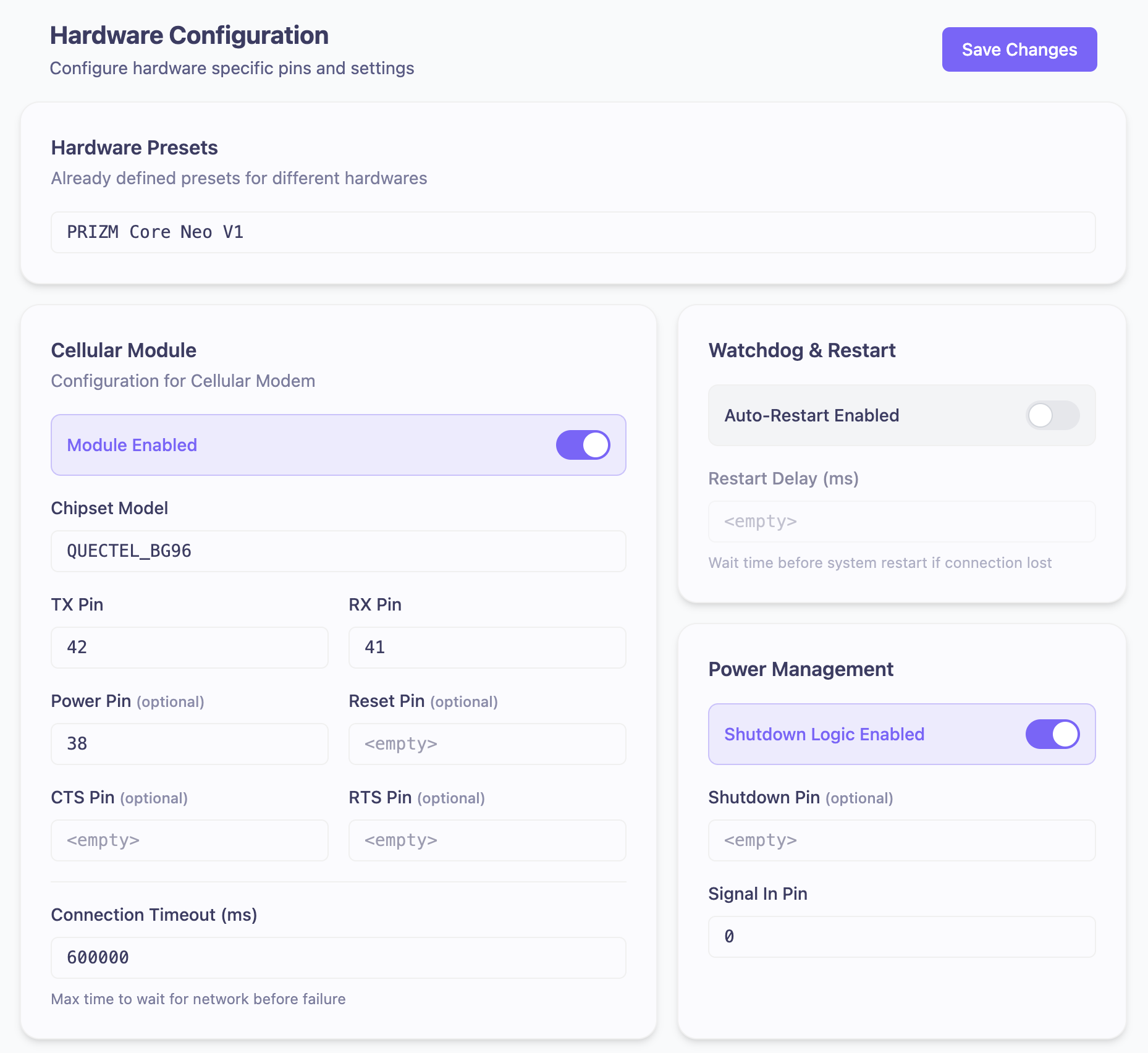
Cellular Module
Settings for the cellular modem. Every field is greyed out while Module Enabled is off.
| Setting | What it does |
|---|---|
| Module Enabled | Turns the cellular modem on or off. |
| Chipset Model | The modem fitted to your board — QUECTEL_BG96 or SIMCOM_7672G. |
| TX Pin | GPIO carrying data from the ESP32-S3 to the modem. |
| RX Pin | GPIO carrying data from the modem to the ESP32-S3. |
| Power Pin (optional) | GPIO that powers the modem on. Required in practice — see below. |
| Reset Pin (optional) | GPIO that resets the modem. |
| CTS Pin (optional) | Clear-to-send flow control. |
| RTS Pin (optional) | Request-to-send flow control. |
| Connection Timeout (ms) | Max time to wait for network before failure. |
Only QUECTEL_BG96 is functional today. If you select SIMCOM_7672G, the
device accepts the setting and saves it, but cellular stays disabled no matter
how the rest of the card is filled in.
Watchdog & Restart
| Setting | What it does |
|---|---|
| Auto-Restart Enabled | Restarts the device automatically when it loses its connection. |
| Restart Delay (ms) | Wait time before system restart if connection lost. |
Power Management
| Setting | What it does |
|---|---|
| Shutdown Logic Enabled | Turns the shutdown behaviour on or off. |
| Shutdown Pin (optional) | GPIO driven by the device as it powers down. |
| Signal In Pin | GPIO watched for the shutdown request. |
Holding the signal-in pin low gracefully shuts the device down, so it can disconnect from the cloud
and detach from the cellular network before losing power. On Core Neo this is the SOFT_SDN signal
behind the SIG button — see
Soft Shutdown Pin.
Wi-Fi
The Wi-Fi network the device joins during normal operation. This is not the Soft AP network you are currently connected to — see Soft AP mode.
| Setting | What it does |
|---|---|
| Module Enabled | Turns Wi-Fi on or off. |
| SSID | Name of the network to join. |
| Password (optional) | Network password. Use the Show / Hide button to check what you typed. |
Status LED
The device’s status indicator. For what each colour and blink pattern means, see LED status indicators.
| Setting | What it does |
|---|---|
| Module Enabled | Turns the status LED on or off. |
| Channel | RMT channel driving the LED. |
| Pin | GPIO the LED is wired to. |
| Brightness (0 - 100) | LED brightness as a percentage. |
Peripheral Pinout Mapping
Assign GPIOs for communication buses. Each bus has its own Enabled toggle, and its pin fields are greyed out while that toggle is off.
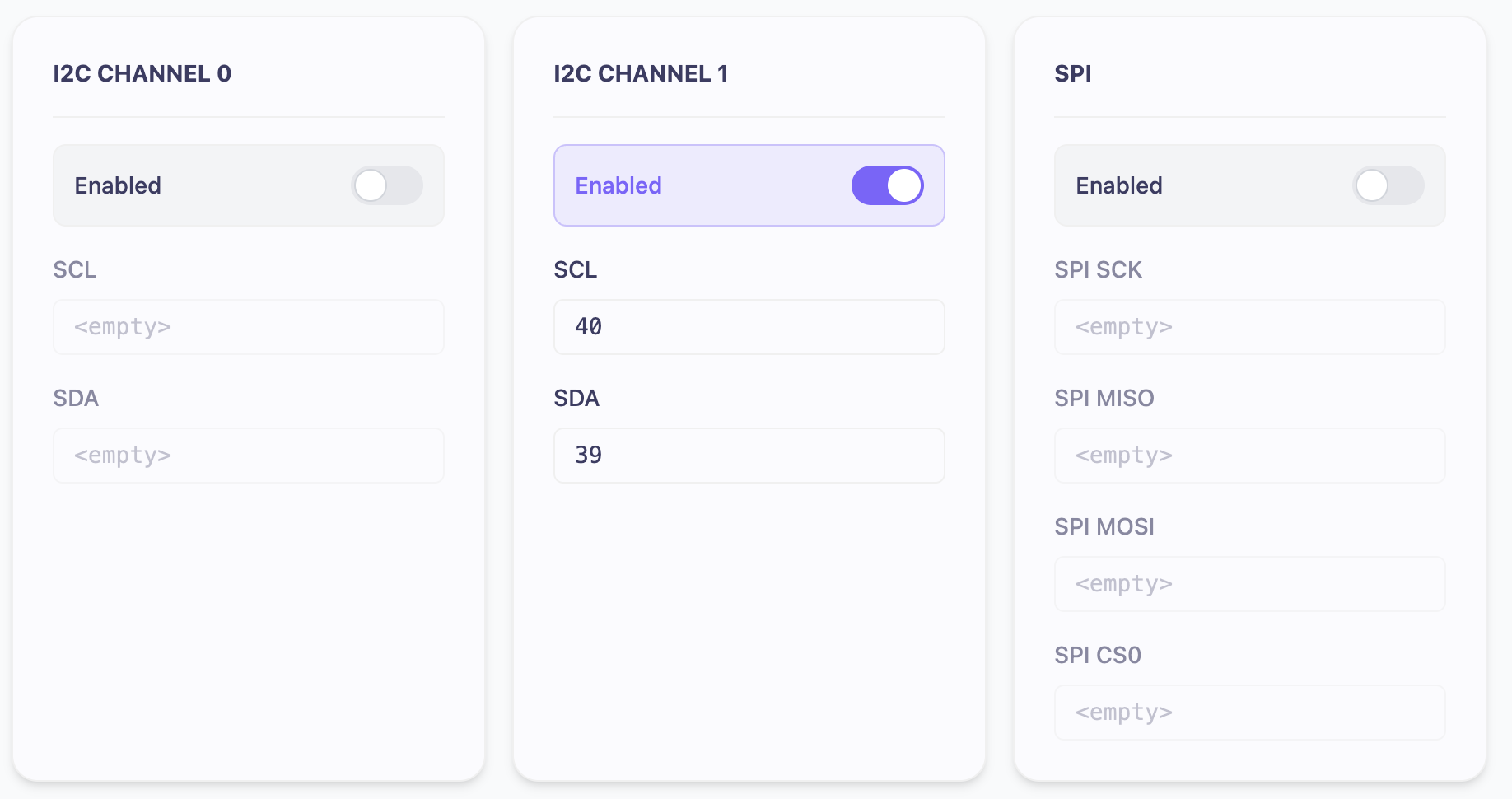
| Bus | Pins |
|---|---|
| I2C Channel 0 | SCL, SDA |
| I2C Channel 1 | SCL, SDA |
| SPI Channel 0 | SPI SCK, SPI MISO, SPI MOSI, SPI CS0 |
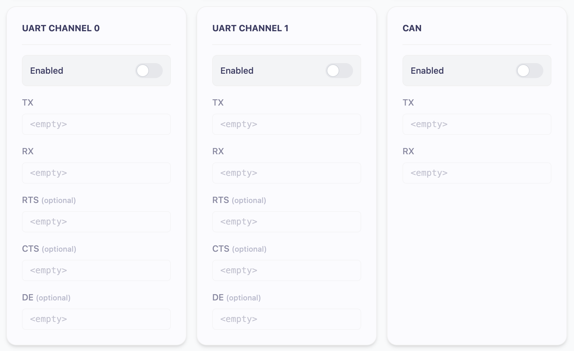
| Bus | Pins |
|---|---|
| UART Channel 0 | TX, RX, RTS (optional), CTS (optional), DE (optional) |
| UART Channel 1 | TX, RX, RTS (optional), CTS (optional), DE (optional) |
| CAN | TX, RX |
Channel numbers match your blueprint
The channel numbers on this page are the ones your blueprints refer to. A peripheral-aware prefab’s channel constant is set in the node, but its bus parameters (baud rate, timing, and so on) are set in the Blueprint Editor’s Global Peripheral Configuration panel — that number picks the card above:
| Channel in peripheral settings | Bus used on the device |
|---|---|
0 | UART Channel 0 / I2C Channel 0 / SPI Channel 0 / CAN |
1 | UART Channel 1 / I2C Channel 1 / SPI Channel 1 |
The blueprint supplies the channel number; this page supplies the pins that channel runs on. Both halves have to be filled in for the bus to work.
The device has two independent SPI controllers, so spi:0 and spi:1 can
both be used at once — but pin mapping for SPI Channel 1 is still
rolling out to this page. Until a second SPI card appears here, only
channel 0 can actually be wired up; a prefab set to spi_channel: 1
deploys but reads nothing until then. CAN has a single channel (0) on
current hardware.
If a blueprint asks for a channel whose card here is switched off or missing
pins, the bus never starts and the prefab reads nothing — the deploy itself
still reports success. Any channel number other than 1 falls back to channel
0 instead of reporting an error, so a typo reads the wrong bus silently.
Entering pin numbers
Every pin field is a plain text box. There is no dropdown of valid pins, no range check and no warning when two peripherals claim the same GPIO, so it is worth knowing the rules before you save.
- Valid GPIOs are 0–21, 38–44 and 46–48. Any other number is rejected when the device
boots: the peripheral fails to start and
Invalid gpio pinappears in the device log. - Nothing stops you assigning one GPIO to two peripherals. The form saves cleanly and the conflict only shows up as a failure at boot.
- Text that is not a number is silently discarded — the field ends up empty rather than rejected.
- Leave a field blank to unset a pin.
A bus only starts if all of its required pins are filled in. CAN and UART need TX and RX, I2C needs SCL and SDA, SPI needs all four, the status LED needs channel, pin and brightness, and Wi-Fi needs an SSID. A half-filled card is treated as disabled, with nothing in the interface to say so.
The cellular Power Pin is labelled optional but is one of these required pins — leave it blank and the modem never comes up.
Saving changes
Save Changes at the top of the tab saves both parts of the form; there is no separate button for the peripherals section. Your browser shows a confirmation once the device has stored the new configuration.
Saving writes the configuration to the device but does not apply it. The new pin assignments take effect on the next boot — open the Device tab and press Reboot Device.