G1 Industrial Gateway
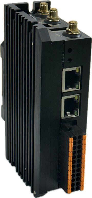
Spec
Basic
| Dimensions | 68mm x 35mm x 123mm x (W x H x L) |
| Operating Temperature | -20 to +80°C |
| Mounting | DIN-Rail, Wall-mount |
| Supply Voltage | DC 12V-60V |
| Power Consumption | Average 1.2W, Maximum 12W (during cellular data transmission) |
Wireless
| Cellular | Type | LTE Cat. 1 (10Mbps DL, 5Mbps UL) |
| FDD | B1/B2/B3/B4/B5/B7/B8/B12/B13/B18/B19/B20/B25/B26/B28/B66 | |
| FDD | B34/B38/B39/B40/B41 | |
| Wi-Fi | 2.4GHz Wi-Fi 802.11b/g/n | |
| GNSS | GPS/GLONASS/Galileo/BeiDou |
Interface
| Ethernet | 1 x 100M RJ45 |
| USB | 1 x USB2.0 Host A-Type |
| CAN | 1 x CAN (isolated) |
| RS485 | 1 x RS485 (isolated) |
| Digital Input | 4 x DI (isolated) |
| Digital Output | 6 x DO (isolated) |
| Analog Input | 4 x AI (isolated, 0-20mA default, 0-10V optional) |
| Analog Output | 2 x AO (isolated, 0-5V output) |
Front
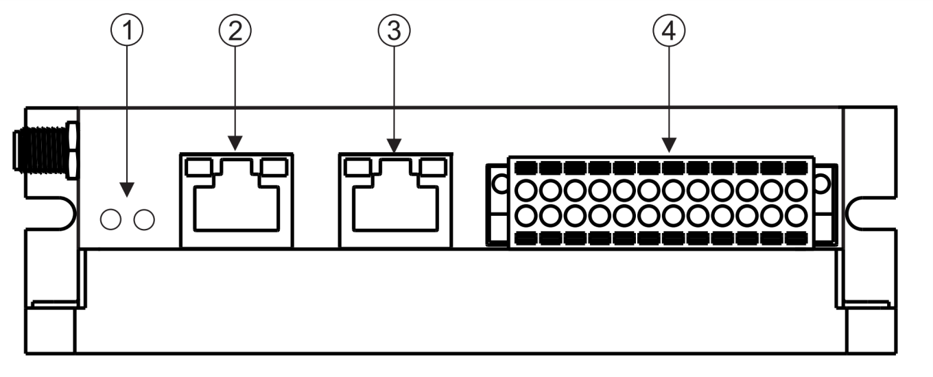
- LED Indicator (Power, Status)
- Ethernet
- CAN & RS485
- Analog & Digital I/O (Phoenix Connector)
Pheonix Connector
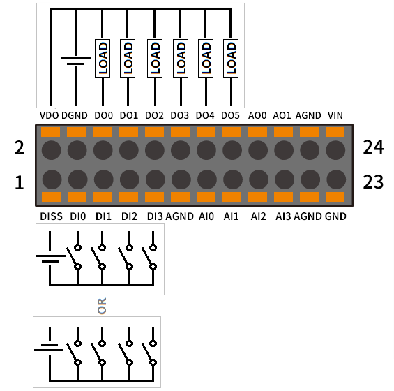
| Pin # | Domain | Name | Description | Pin # | Domain | Name | Description |
|---|---|---|---|---|---|---|---|
| 1 | Digital | DISS | Digital input source for DI0-DI3 | 2 | Digital | VDO | Digital output power for DO0-DO5 |
| 3 | Digital | DI0 | Digital input 0 | 4 | Digital | DGND | Digital output ground for DO0-DO5 |
| 5 | Digital | DI1 | Digital input 1 | 6 | Digital | DO0 | Digital output 0 |
| 7 | Digital | DI2 | Digital input 2 | 8 | Digital | DO1 | Digital output 1 |
| 9 | Digital | DI3 | Digital input 3 | 10 | Digital | DO2 | Digital output 2 |
| 11 | Analog | AGND | Analog ground | 12 | Digital | DO3 | Digital output 3 |
| 13 | Analog | AI0 | Analog input 0 | 14 | Digital | DO4 | Digital output 4 |
| 15 | Analog | AI1 | Analog input 1 | 16 | Digital | DO5 | Digital output 5 |
| 17 | Analog | AI2 | Analog input 2 | 18 | Analog | AO0 | Analog output 0 |
| 19 | Analog | AI3 | Analog input 3 | 20 | Analog | AO1 | Analog output 1 |
| 21 | Analog | AGND | Analog ground | 22 | Analog | AGND | Analog ground |
| 23 | Power | GND | Power ground | 24 | Power | VIN | Power input (12V-60V) |
*DI0-DI3 can handle I/O voltage up to 50V and DO0-DO5 can handle I/O voltage up to 60V
RJ45 Connectors
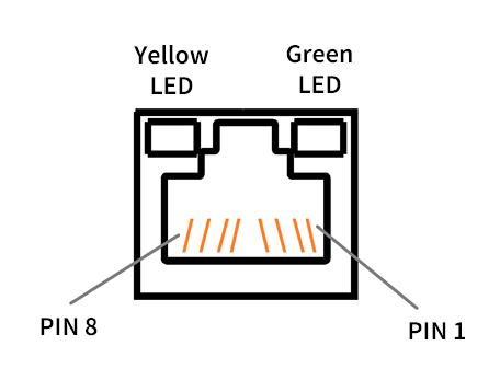
Ethernet
| Pin # | Signal | Description |
|---|---|---|
| 1 | TXP | Transmit+ |
| 2 | TXN | Transmit- |
| 3 | RXP | Receive+ |
| 6 | RXN | Receive- |
| 4/5/7/8 | NC | Not used |
| Yellow LED | Active when TX and RX | |
| Green LED | Active when link up |
CAN & RS485
| Pin # | Signal | Description |
|---|---|---|
| 4 | CANH | CAN high bus line |
| 5 | CANL | CAN low bus line |
| 7 | RS485A | RS485 signal A |
| 8 | RS485B | RS485 signal B |
| 1/2/3/6 | NC | Not used |
| Yellow LED | Active when RS485 TX and RX | |
| Green LED | Active when CAN TX and RX |
Left Side
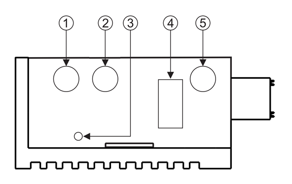
- Wi-Fi Antenna Connector (SMA female)
- GNSS Antenna Connector (SMA female)
- Reset Button
- USB2.0 Host A-Type Connector
- Cellular Antenna Connector (SMA female)
Last updated on